|
|
|
|
Judging by all the pondside questions I'm asked about LEDs, it seems an article about them is long overdue, so here goes! OverviewThere are a number of differences between LEDs and conventional (filament) bulbs which if not understood make them either easy to blow up or liable to not work at all. That is not to say they are tricky or unreliable, you just need to learn to use them properly. On the plus side, for all practical purposes we can consider that their lifetime is infinite (an important consideration if they are built into a region of your boat with difficult access). This is especially true where lights are required to flash - the starting current surge into a cold filament is the most common cause of bulb failure, whereas LEDs are immune from this problem. The next most common cause of (hot) filament failure is vibration, and once again by virtue of being 'solid state' LEDs are immune. Neither do LEDs 'age' like filament bulbs. When the latter are run on DC, metal from the filament evaporates and gets deposited on the inner surface of the glass giving a silvering effect and reducing the light output, plus the filament is now thinner and increasingly likely to fail in either a starting surge or under vibration. Filament bulbs are available in 'white' light only, and colours have to be created by use of a filter, which reduces the light intensity, whereas LEDs are available in most of the colours needed by modellers - red & green for navigation lights, white for interior lighting, spotlights etc. and in blue for (flashing) beacons. LEDs are more efficient too, requiring only a fifth to a tenth of the power of a filament bulb for a comparable light output - but given that the light is emitted in a conical beam rather than spherically then the perception of brightness will depend on the angle that the LED is viewed at. The additional power taken by filament bulbs is dissipated as heat, LEDs run cold. This directional light output is the biggest drawback of LEDs, whereas filament bulbs shine equally in all directions. As a guide LEDs have viewing angles from around 40 to 120 degrees depending on their packaging, after which their perceived intensity falls off quite rapidly. In practice this might mean that in an interior lighting scenario, white LEDs would need to lined up with the portholes rather than be placed anywhere in a random orientation within the cabin. If wide visibility of a point source of light (e.g. navigation lights) is required, then Maplin offer a range of LED covers (intended for equipment front panels) which increase the viewing angle to 180 degrees by means of a flat top marked with Fresnel rings and striated lines which maximize the light dispersion. LED CharacteristicsThe term 'LED' is an acronym for 'Light Emitting Diode', and that is the single biggest clue as to how they operate - just like a diode! Like regular diodes, LEDs can only conduct (and thereby emit light) when they are forward biased (i.e. when their anode is positive with respect to their cathode) so the immediate consequence of that is that, unlike filament bulbs, LEDs will only light up if the correct polarity of voltage is applied to them. The polarity of an LED package is identified in two ways. The cathode is the shorter of the two leads and in the case of the most common cylindrical types, the base of the LED has a small flat next to the cathode. For other parts consult the published specifications.
To drive the idea home, imagine (don't try!) wiring an AA cell across a 12v car battery. You just know that is WRONG. Try and think that way about LEDs. But at this point I'm sure many of you will say you have an LED torch that just puts the LEDs directly across the battery. Well, it might be possible that small (non obvious) surface mount resistors have been used, but some torches do not use resistors at all. What the designers have done here is to have closely matched the battery voltage to the LED voltage drop and then relied on the 'feebleness' of the AAA cells to limit the current when supplying that group of LEDs. Try that trick with Sub-C NiMH race packs or 7Ah Lead Acid Cells, whose voltage doesn't sag appreciably when you load them, and you'll be using smoke emitting diodes! Just to complicate matters, different colour LEDs have slightly different voltage drops. Red LEDs take the least, and as the colour moves through the colour spectrum toward blue, the voltage requirement increases. White types are really blue ones exciting a yellow phosphor which approximates to white light. Typically, a red LED requires about 2 volts, whilst white/blue ultra-bright LEDs are heading towards 4 volts. Most LEDs are housed in a diffused epoxy case of the appropriate colour, but some are housed in clear epoxy regardless of the colour of light they emit - a point to consider for static display of your model. Again, the tinted Maplin LED covers could help. The operating conditions required by your LED will vary by size, brightness, colour, manufacturer etc. so check your catalogue (or web page), but as a generic 'one size fits all' guide, you will not go far wrong by assuming an operating current (usually denoted as If ) of 20mA and for the operating voltage (usually denoted as Vf ) the following is a guide
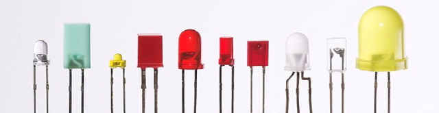
These guideline figures will increase the higher the operating current and different manufacturers quote these voltage drops under different current conditions, so read that data sheet! LEDs come in all shapes and sizes, but the cylindrical 3mm or 5mm with domed ends are probably the most common. A quick check shows Maplin offering 2, 3, 5, 8 and 10 mm types. The LED chip sits in the bottom of the cylinder, which has reflective sides to shine the light emitted by the chip toward the dome end of the LED. The epoxy body is shaped to act as a lens and focus the light into a beam. The distance from the chip to the domed end of the lens determines how tightly focused is the resulting beam of light. Some LEDs have flat or even concave ends to disperse the light into a wider beam. Thus low profile surface mount types with flat tops give around 140 degree viewing angles whereas cylindrical types with domed tops might only give 60 degrees. Rapid Electronics sell a wider range of case styles including rectangular ones and at the miniature end of the range surface mount types that are around 1mm square and 1/2mm thick. Also there are special purpose LEDs with built in resistors so they can be wired directly across 5v or 12v for example. Even cleverer devices have built in constant current sources that drive the LED at a steady current no matter what supply voltage you use (within reason!) Again, others have built in flasher circuits - but I will confine this discussion to general purpose LEDs. Designing Your Lighting SystemThe main issue here is to best match the number of LEDs and their mode of connection to the available battery supply voltage. LEDs can be each run singly via a current limiting resistor but that can be wasteful of power (dissipated in the resistor) . It may be possible to add several LEDs in series and use a lower value resistor for the same overall power consumption as in the first case. If the combined voltage drop of all your LEDs exceeds the battery voltage then you will need to put several series chains of them across your battery. The resistor value for any series chain of LEDs for a typical LED current of 20mA is calculated thus:
This will give the required resistor value in ohms - choose the nearest preferred value resistor available.
It is advisable to allow 2 or 3 volts across the series resistor such that it can set the current with reasonable definition. Otherwise changes in the battery supply voltage would cause wild fluctuations in brightness - anywhere from off to blown!
|
|||||||||||||||||||||||||||||||||||||||||||||||||||||||