|
Firstly I must acknowledge that there are some of you who are philosophically opposed to BECs and prefer to use a separate receiver battery pack. Personally I don't have years of model boat experience to be able to make that judgement, so if you are at all nervous please ask the opinions of a few experienced club members before you embark on this project.
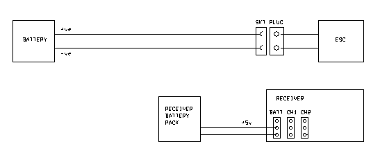
Still with me? OK, below I have a diagram showing how a typical boat using a receiver battery pack is wired up.
To convert to BEC operation I am presenting a 'plug-in' solution to work in existing installations without modification. If you have numerous boats, such a unit can be moved around as required, provided you have standardised on your connectors. Personally, I wire the BEC in directly to avoid the losses and unreliability associated with the extra connectors - but the choice is yours.
In the diagram below the main components of battery, ESC and receiver are shown in the same positions as before, and the BEC system is shown in red. You will note that a plug/socket pair pass the battery power through to the ESC as before. Be sure to use similar gauge wires for this part of the BEC as the battery and ESC. The remainder of the BEC is very low current so thinner wire can be used for this.
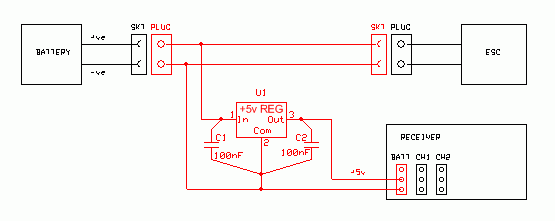
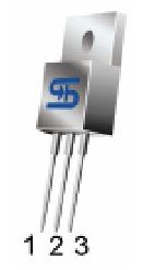 The heart of the BEC is a +5v voltage regulator (U1) and at a cost of a pound or less is definitely cheaper than four batteries. This is a three pin semiconductor device which accepts your battery input voltage and drops it down to +5v. It is a stabilised regulator so the output will remain at +5v regardless of variations in loading (eg during servo movement) and temperature - up to the current capability of the device that is!
As this is a linear (ie not switching) regulator, the voltage dropping is a lossy process and it may get warm or even hot depending on the operating regime of your boat. Normal current drain from the receiver, ESC and stationary servo(s) is usually low so the losses are fairly small. Slewing a rudder servo, especially against the hydro-dynamic forces at high speed will take a lot more current, so the losses will be higher. ESCs using a relay for reversing sometimes (but not always) use the +5v receiver supply to power the relay coil so be sure your motor is wired correctly so that the relay is de-energised in the 'forward' direction to save power and BEC losses in normal operation.
 It is advisable to fit a small heatsink to U1 - eg Maplin KU50E (55p), but you may well get away without doing so. If you choose to risk it, then check how hot the device feels after a short run with energetic rudder activation. The regulator chip is protected against thermal overload and will shut down if it gets dangerously hot so your boat could come to an unexpected halt, but the regulator is 're-entrant' so it will start up again when it cools down.
Such regulator devices do need some voltage 'headroom' in order to operate (ie an input voltage in excess of the +5v output). There are two alternative parts you can use dependent on your battery voltage. The cheaper part, TS7805CZ - Maplin QL31J (59p) has a very poorly specified 'drop-out' voltage, quoting only a 'typical' value (not a 'max') of 2v when supplying 1 amp and would therefore be best suited to 8.4v batteries and above. A special low drop-out voltage version, TS2940CZ-5.0 CO - Maplin N67CA (92p) is far more tightly specified and taking the 'max' or worse case condition only drops 0.8v at 1 amp and 0.5v at 500mA or 0.2v at 100mA - 'typical' values are almost half of those. Bear in mind the better parts could quite likely be selected out from the manufacturing output of the TS7805CZ, so the latter may well all have poor 'drop-out' performance. If your battery voltage is high enough, that isn't a problem, but 7.2v NiXX and 6v lead-acid users should definitely use the TS2940CZ-5.0 CO.
C1 and C2 decouple the regulator and prevent any tendancy for it to oscillate (especially if used with long input and output wires). Omit them and any oscillation may not be immediately apparent, you measure a solid +5v output, but the device may get hot even without supplying any load and the RF emission from it may cause interference problems. Use disc ceramic type capacitors, as used for motor suppression - Maplin BX03D (11p). To be effective the capacitors should be placed as close as possible to the regulator pins (as the slanty lines on the circuit diagram are supposed to suggest).
The BEC module may be constructed around the chip itself, soldering the capacitors directly across the pins and add flying leads to your battery, ESC and receiver. The pin spacing is 0.1" pitch so be careful not to splash solder across adjacent pins and sleeve them with heatshrink tubing afterwards to prevent them touching due to handling abuse. You may wish to use a small scrap of veroboard (copper clad matrix board) to mount the regulator and capacitors on and terminate your leadout wires - if so, run a bead of solder along any track carrying the battery to ESC current as the tiny holes almost to the edge of the tracks make great fuses! If you then want to put it in a small plastic box, don't be tempted to put the heatsink inside it - it requires to be in free air!
|