|
|
|
|
Dual R/C SwitchIntroduction
On the desired R/C channel of the receiver a "Y" lead must be fitted such that the receiver feeds both the original servo PLUS this circuit. Next, simply adjust the potentiometer(s) until the relay(s) pull in at the desired transmitter stick position(s) - the LED(s) will indicate the relay(s) are energised if you can't hear them click. The circuit's relay contacts are then wired up as normal to invoke the desired auxiliary functions - eg a light, a sound, a pump . . . . . Moving a stick on the transmitter causes a variable width pulse between 1 mSec to 2 mSec (neutral = 1.5 mSec) to be output from the appropriate receiver channel. This circuit works by monitoring that pulse width and if it is greater than a preset value (eg 1.7 mSec) a relay is turned on, whereas if it is less the relay is turned off. A small amount of hysteresis or "dead zone" has been introduced around the switching point so that the control is not "hair trigger" sensitive. Circuit Diagrams
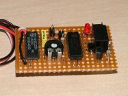
Circuit Description(Single switch circuit description refers) The leading edge of the input signal pulse triggers a 74HC123 precision monostable (U1) which produces an output pulse (pin 4) whose width is determined by RV1, R1 and C3. RV1 gives adjustment in the range 1 mSec to 2 mSec. Lets suppose it's set for 1.7 mSec and currently the input pulse is 1.5 mSec. At the end of the monostable time (1.7 mSec) a 74HC74 D-type latch checks to see if the input pulse (1.5 mSec) is still active - no it's not so the D-type latch takes no action. Now the input pulse increases to 1.8 mSec. Again its leading edge fires the monostable and 1.7mSec later the monostable times out and the D-type latch now finds the input signal is still active, so the latch is "set" and via transistor Q1 turns on relay RL1. D2 and R2 now come into play and slightly shorten future monostable pulses (eg now 1.69 mSec) which means a clean switching action results with no dithering about the trip point. D4 protects Q1 against (inductive) voltage spikes caused by switching off the relay. LED D3 indicates the state of the relay. C1 and C2 locally clean up the +5v supply voltage to ensure noise does not affect the stability of the timing period. C3 must be a low temperature coefficient type capacitor as specified or otherwise you will find you have built a thermometer rather than a switch - ie you set the switch up at home and when you get to the pond it doesn't work (the trip point has changed because it's colder outdoors than in). Note that I have shown the simplest scenario where the relays have 6v coils and can therefore run from the +5v R/C supply. Contact me for info on adapting the circuit for use with +12v relays (generally the automotive types needed for high current switching capability) or if you wish to use a power FET to switch your load to Ov. ConstructionThis unit is best built on verboard (as per the DIY Servo Tester, see that project for an example of its use) the style of layout largely being determined by the desired overall size including the chosen relay type both of which are probably a function of your boat and the switch's intended application. An experienced electronics constructor with good eyesight and a steady hand can always build a surprisingly small unit, whereas a novice will find it easier to allow plenty of space. TestingI am writing this without the benefit of a prototype in front of me - they both got given away! Also I had the luxury of an using an oscilloscope - but if you owned one you wouldn't be reading this anyway! So here are my thoughts on testing your handiwork with a multimeter, which I assume you have got. Ideally you will have a servo tester - no? - well build that first and you will get familiar with veroboard construction as I have an example layout worked out already. Otherwise you will need your transmitter and your receiver. Set RV1 to mid position and plug the unit into your servo tester or the appropriate receiver channel with (in both cases) the controls centralised. Now vary the tester/transmitter control from end to end of its range and if you are lucky, somewhere near the centre of the range you will hear the relay click on and off (or watch the LED if you are getting deaf). If it works, try setting RV1 to either side of centre position and note the switching point on your tester/transmitter has changed accordingly. No joy? After carefully inspecting your layout for constructional errors like uncut tracks or solder bridges between tracks, it's time for getting out your multimeter. First check that +5v appears on the pins of U1 and U2 that are assigned to +5v (U1 - 3,16) and (U2 - 1, 4, 14). Then check that (U1 - 1,8) and (U2 -7) are connected to Ov. Now with the orginal starting conditions you should be able to measure about 0.26v on pin 2 of U1. Verify that this voltage swings down to 0.17v and up to 0.34v as you move the tester/transmitter control from end to end. These readings will vary a little depending on the value of your +5v supply (mine that gave these readings was only 4.7v) and the current drive capability and frame rate of your tester/receiver. The precise values aren't important, just that they are of this order of value, and you now have an indication that the input pulse train is varying between 1mSec and 2mSec and has successfully reached the monostable input pin. Next we check the monostable output pulse. Centralise your tester/transmitter control again and measure the voltage at U2, pin4. This should read about 4.4v (4.7v-0.26v) as the 1.5mSec output pulses are negative going this time. Now vary RV1 from end to end and you should be able to get a similar +/- 0.1v swing around the 4.4v. If so, your monostable (U1) is working. Next check the the input signal 0.17v to 0.34v input signal is reaching the latch circuit (U2, pin2) and that the monostable out we just measured around 4.4v is reaching U2, pin 3. If so, is the latch operating? - check the voltage at U2 pin 5 swings between Ov to 5v as you vary the tester/transmitter control. If it does, then the problem is with Q1 or the relay. Parts List
|
||||||||||||||||||||||||||||||||||||||||||||||||||||||||||||||||||||||||||||||||||||||||||||||||||||||||||||||||||
 If you build a dual switch, you can choose to have the two switches both assigned to the same input channel (eg to actuate both the relays at points on the left/right function - or you can assign the switches to work on two independent channels (eg the transmitter on/off channels 5/6 controlled by toggle switches)