
|
|
|
|
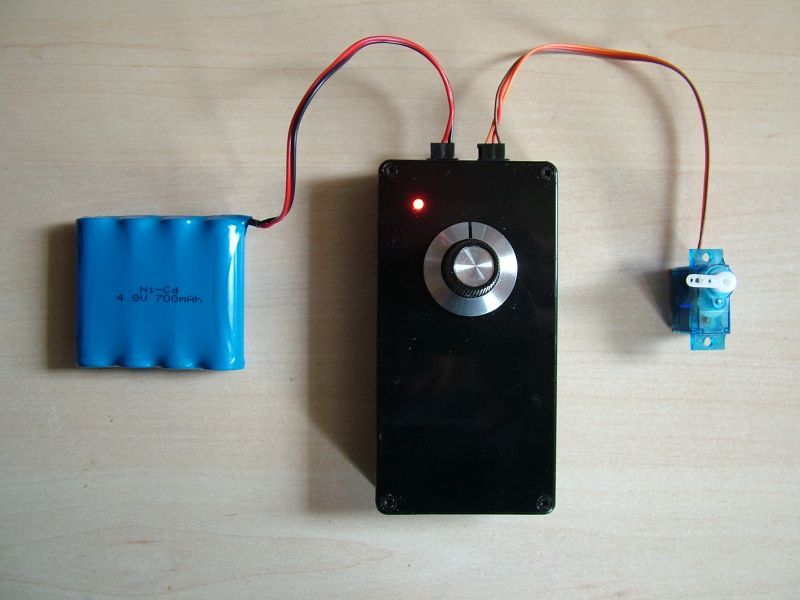
DIY SERVO TESTER
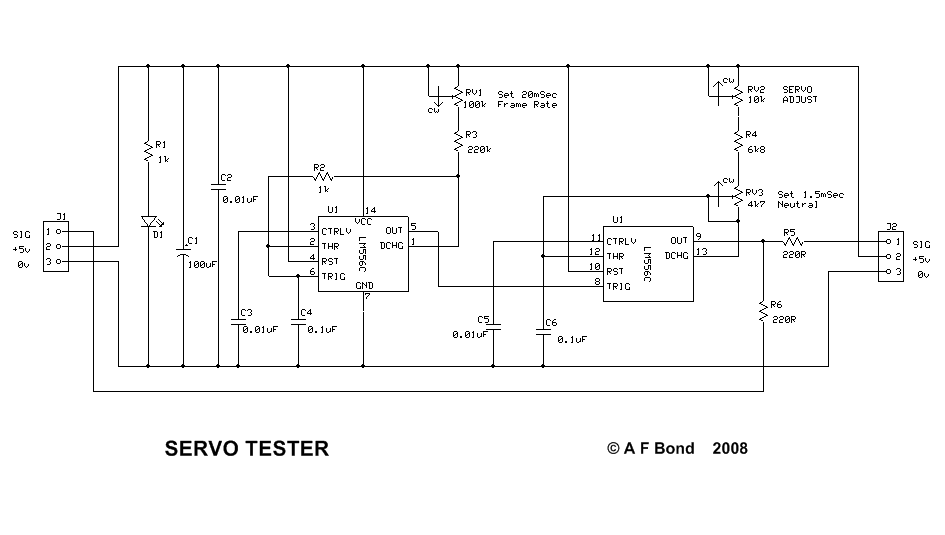
Circuit Diagram
Circuit DescriptionPower is supplied through either J1 or J2 and LED D1 indicates the presence of +5v on the circuit. C1 and C2 smooth the supply from low frequency and high frequency disturbances respectively. The oscillator formed from the first section of U1 has its frequency set by C4, R2, R3 and RV1. The frame rate is not too critical so RV1 could be replaced by a 47k resistor to simplify the circuit, but it *is* important to use the type of capacitor specified for C4 to avoid the frame rate varying with temperature. C3 decouples the timer's reference voltage to reduce possible frequency jitter due to noise. The monostable formed from the second section of U1 has its timing period set by C6, RV3, R4 and RV2. Again, for temperature stability be sure to use the recommended capacitor type. RV2 is the user control, and it can be set to give servo neutral/centre at its mid position by adjustment of RV3. C5 decouples the timer's reference voltage to reduce possible pulse-width jitter due to noise. The output pulse connects to the servo under test via R5 or R6, depending on the socket used. Construction
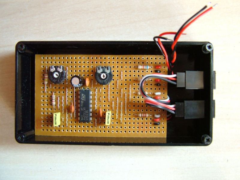
The second picture shows the board mounted into a small plastic box which has had two slots cut in its side to take the two flying sockets which have then been glued in. Be sure to mark the outside of the box so you can identify the orientation of the red, white and black leads. The LED and pulse width adjusting potentiometer are mounted on the lid of the box (see picture of completed unit at top of page)
It is best to start off with the blank board and cut the track breaks first. Then fit the components in order of lowest height, soldering each one in as you go - this way when you turn the board over to solder, the component rests on your workbench and doesn't drop out. So that means links first, then the resistors, the integrated circuit, the preset potentiometers and finally the capacitors. It is all too easy to inadvertently join adjacent tracks (that shouldn't be!) with a thin splash of solder or a shard of cut copper, so before you power it up for the first time, check the copper side of the board very carefully. A suede shoe brush can be useful to rub along the direction of the tracks to clear out soldering debris, especially flux. TestingSet RV1 and RV3 to their mid positions. Connect a 4 cell receiver pack to either of the connectors and check that D1 lights. If not, have you got the battery plug polarity correct? Without an oscilloscope it is difficult to determine if the oscillator section is working so connect a known good servo to the second connector and by turning RV2 it should be possible to drive the servo from end to end. With RV2 set to mid-position, check that RV3 is capable of adjusting the servo to it's neutral position. If you have access to a commercial tester with a pulse-width readout, then RV2 and RV3 can be more accurately set up by using your unit to drive the former. Parts List
|
 To test a servo we require to generate a signal similar to the receiver output. That is, a pulse varying between 1 to 2 mSec, repeated every 20mSec.This is achieved using a dual 555 timer chip. One timer is set up as an oscillator running at 50Hz (ie 20mSec) and its output fires the second timer which is configured as a monostable, whose period is adjustable from 1 to 2mSec.
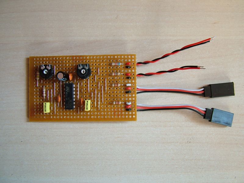
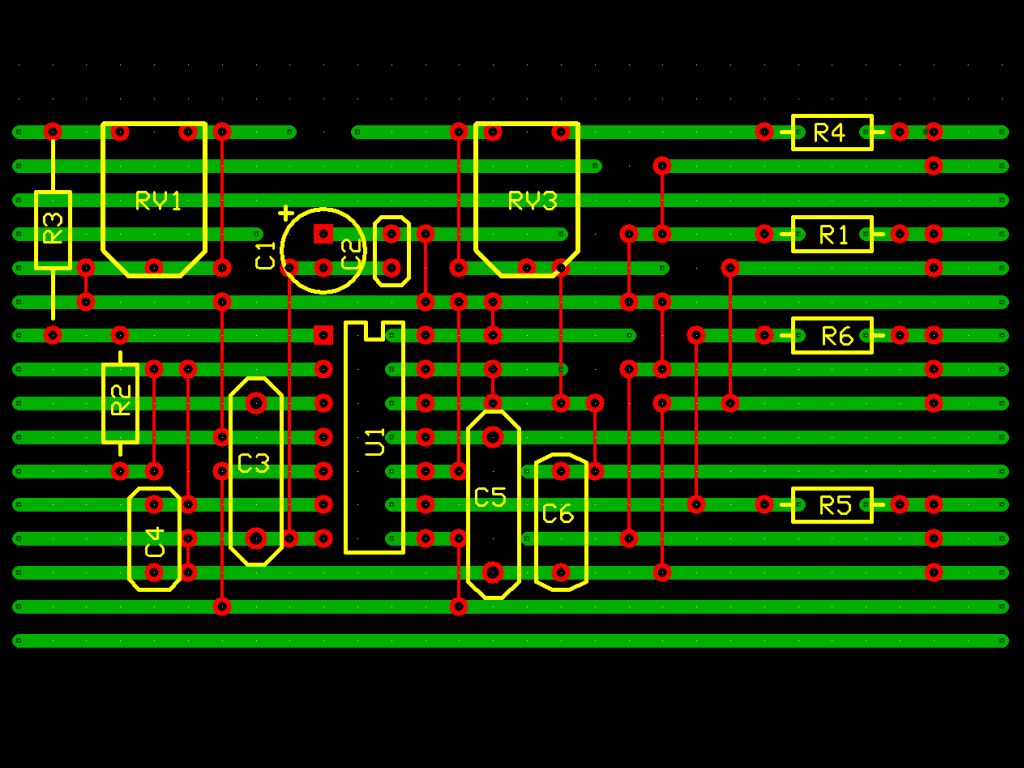 Here is the veroboard layout, viewed from the component side, so the copper tracks (green) are underneath. Everywhere there is a gap in the green, that represents a cut in the copper track - locate a 3mm drill bit in the hole where the cut is required and simply twist in your fingers to remove the copper (don't buy the over-priced purpose made tool). The red lines are wire links, made from single strand tinned copper wire.