|
|
|
|
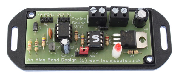
REVISED ENGINE SOUND SIMULATOROverviewThe original sound unit, first posted in these pages in Autumn 2008, and available as a 'hobbyist' self assembly kit, is now available ready-made in a more compact and professional form. This has been achieved by omitting the chip re-programming and auxiliary audio out sockets which were, it seems, rarely used and by designing a printed circuit board (PCB) for the remaining circuitry. The PCB did away with the 27 track cuts and 15 wire links on the stripboard layout, as well as allowing more dense component placement. At the same time the lead terminations have been improved and the whole unit now fits in a neat 80mm x 40mm flanged ABS box. Just to recap, this is a universal engine sound module that can produce a variety of different engine sounds. In all cases the hardware module remains the same and the type of engine sound and its character are varied by firmware (i.e. the fitted software) alone.
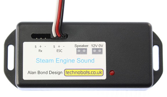
The unit can be used with any radio system, including PCM, that utilises the industry standard 1 to 2mSec servo signal. In other words all commonly used R/C transmitters and receivers. 'Neutral' (i.e. joystick at centre position) is assumed to be set at 1.5mSec and this condition is indicated by a case mounted LED which assists in setting the transmitter throttle trim. The unit is easily installed by removing the Electronic Speed Controller (ESC) lead from your receiver and plugging in a lead from the sound unit in its place. The ESC lead then plugs into the sound unit, thereby obviating the need for a Y lead. The unit's electronics takes its power from the receiver, but the loudspeaker derives its power from either the model's main propulsion battery or a separate battery pack. Connections for speaker power and the loudspeaker itself are made using screw terminal blocks and the wires exit through milled slots in the side of the case.
The following videos show the unit in action:
Units are available from Technobots and include a 12 page colour booklet covering installation, set-up and advice on loudspeaker selection and mounting. Specificationsspeed demand sensing method - receiver throttle channel (unit has pass-through to ESC) neutral (idling) signal condition – 1.5mSec receiver voltage - (which powers the unit's electronics) 4.8v min to 6v max (this is usually supplied by a BEC which is often incorporated in the ESC) speaker impedance - 8 ohm minimum (Technobots part no. 2400-015 recommended) speaker supply voltage - from zero to 12v (governs the volume of the unit) power output - approx 4W RMS @ 12v into 8 ohms (equates to 160W PMPO in today's modern hi-fi advertising terms!) engine types - 'petrol', 'diesel', 'steam' number of cylinders - petrol & diesel 2, 3, 4, 5 or 6 and steam 1, 2, 3, 4, 5, or 6 (link selection procedures) engine stop / start - automatic, determined by throttle demand and idling period |